Cognitive Updating Test (CUT)
Cognitive Updating Test (CUT)
Overview
The CUT presents six simultaneous data displays, two visible at any time, and scores you on how accurately you maintain each system within tolerance across a timed session.
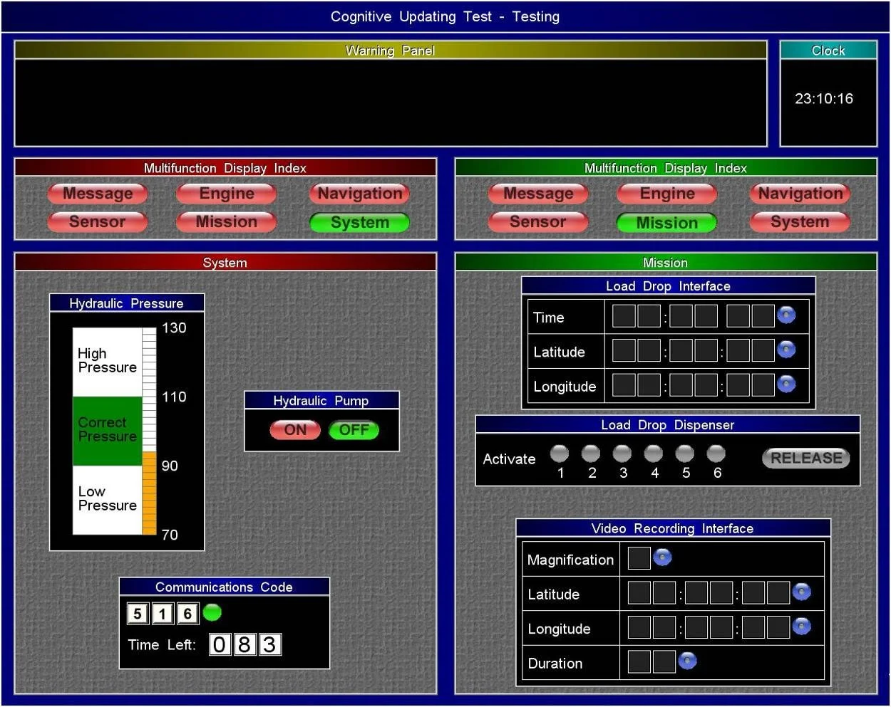
You navigate between displays using the Multifunction Display Index, a row of six labelled buttons (Message, Engine, Navigation, Sensor, Mission, System) that appears at the top of each active panel. Only two panels are open at once. The Warning Panel sits above both panels and flags any system that has breached its threshold; the Clock in the top-right corner runs in real time and governs time-scheduled tasks. Your primary objective is to keep the Warning Panel empty.
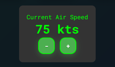
Worked example: the Warning Panel reads "Speed out of range." You open the Navigation display. Current Air Speed reads 75 kts; Required Air Speed reads 90 kts. The tolerance is +/- 10 kts, so the acceptable range is 80-100 kts. You press (+) until the display reads 100 kts, setting the speed at the upper limit to delay the next required correction.
When the Warning Panel displays an alert, you must navigate to the flagged display and correct the deviation before cycling to your next scheduled task. When the Warning Panel is empty, you follow your rotation through each display in sequence.
Warning Panel and Clock
The Warning Panel and Clock are fixed components that remain visible regardless of which displays are open.
The Warning Panel occupies the full width of the top of the screen and is blank during normal operation. The Clock sits in the top-right corner and counts time in HH:MM:SS format. Neither component requires navigation to view; both are always on screen.
Worked example: the Clock reads 23:10:16 and an earlier Message instructed you to drop load at 23:30:00. Nineteen minutes and forty-four seconds remain. You continue your rotation and return to the Mission display when the Clock approaches 23:29:45.
When the Warning Panel displays text, you must treat it as an immediate interrupt and navigate to the relevant display before continuing your rotation. When the Clock approaches a scheduled time, you must be on the correct display within five to ten seconds of that timestamp.
Multifunction Display Index
The Multifunction Display Index is the navigation bar that controls which two displays are active at any time.
It appears as a row of six buttons (Message, Engine, Navigation, Sensor, Mission, System) at the top of each panel. The active display for that panel is highlighted green; all others are red. Clicking any button replaces that panel's current display with the selected one.
Worked example: the left panel shows Engine (green highlight) and you need to check Navigation. You click Navigation on the left panel's index. Engine closes; Navigation opens in its place. The right panel remains unchanged.
When you need a display not currently active, you click its button in either panel's index to replace that panel's current content. When both panels are occupied by displays you need to monitor simultaneously, you close the one with the lower immediate risk.
Message
The Message display is a text panel that delivers task instructions and data values needed to complete fields in other displays.
Instructions appear as plain text and remain visible for an extended period after arrival. You do not need to keep Message open permanently; its content persists long enough to return after cycling through other displays.
Worked example: Message reads "Set magnification to 6." You navigate to Mission, locate the Video Recording Interface, find the Magnification field, and enter 6. You close Mission and return to your rotation.
When a new instruction appears in Message, you must read and memorise the required value before navigating to the target display to action it. When Message contains no new instructions, you close it and open a higher-priority monitoring display.
Engine
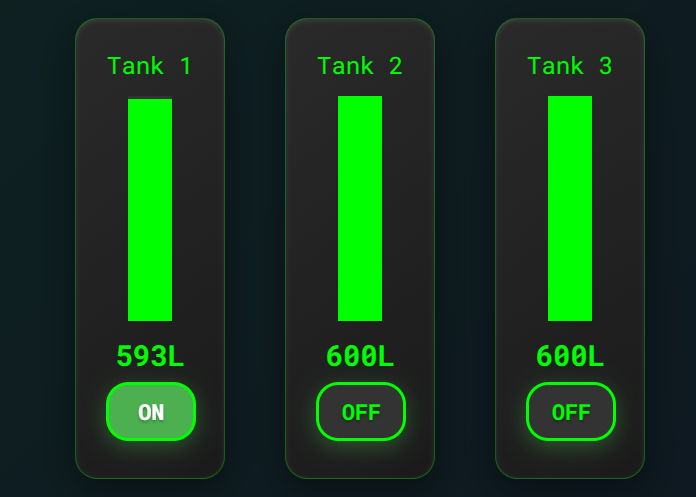
The Engine display shows three fuel tanks, each with a vertical fill gauge and an On/Off toggle, and requires you to keep all tanks within 50L of each other.
Each tank displays a numerical fuel level in litres and a green fill bar. Only one tank can be active (ON) at a time; the active tank drains while inactive tanks hold their level.
Worked example: Tank 1 reads 593L (ON), Tank 2 reads 600L, Tank 3 reads 600L. The difference between Tank 1 and Tank 2 is 7L, inside the 50L tolerance. No action is required. If Tank 1 drops to 550L while Tanks 2 and 3 remain at 600L, the gap reaches 50L and you must act before it widens further.
When any tank's level diverges from the highest tank by 50L or more, you must switch the ON tank to the lowest-reading tank. When switching, you click OFF on the current active tank first, then click ON on the target tank.
Top Tip:Switch the active tank to the one furthest below the others, not the nearest, to maximise the interval before the next required correction.
The the Current Air Speed panel is also found in the Engine Tab and is connected with the task in the Navigation Section.
Navigation
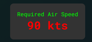
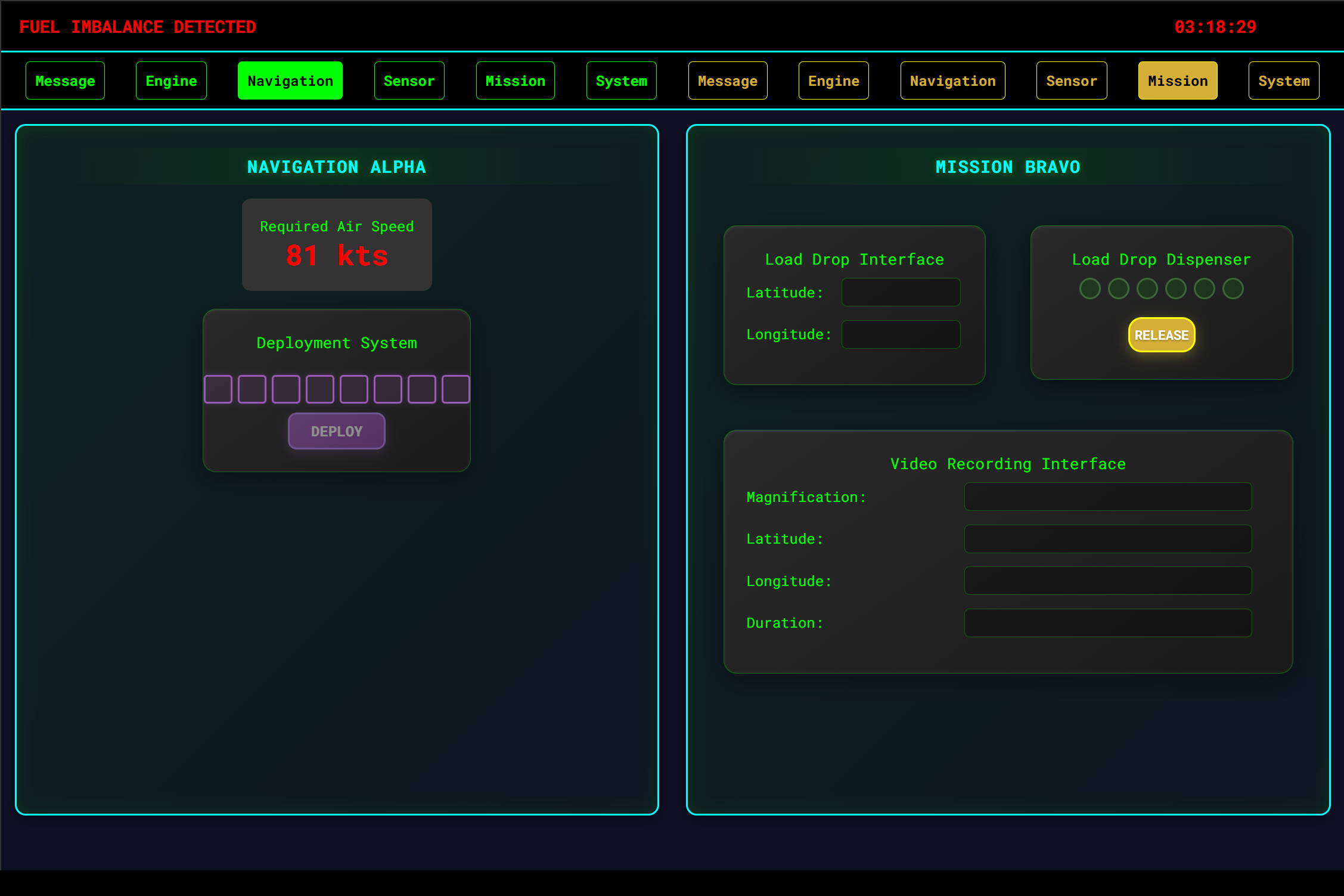
The Navigation display shows the Required Air Speed and requires you to keep the current speed within +/- 10 kts of the required value at all times.
Required Air Speed is a fixed value displayed in red text; it changes periodically without warning. Current Air Speed is displayed in green text and decreases gradually over time without input. Speed is adjusted using the (+) and (-) buttons.
Worked example: Required Air Speed reads 90 kts. Current Air Speed (in the Engine Tab) reads 75 kts. The acceptable range is 80-100 kts. Current speed is 5 kts below the lower bound. You press (+) until Current Air Speed reads 100 kts, placing it at the upper end of the tolerance band. The speed can now drop 20 kts before falling out of range again, maximising the interval before your next required visit.
When Current Air Speed falls below the required value minus 10 kts, you must press (+) to raise it. When you raise speed, you must target the upper ceiling of the tolerance band, not the midpoint. When Required Air Speed changes, you must recalculate the new tolerance band immediately before continuing your rotation.
Top Tip: Always set Current Air Speed to Required Air Speed plus 10 kts after each correction. This places you at the top of the tolerance band and gives the speed the full 20 kt width to fall before another correction is needed.
Navigation Tab also has an 8 box loading window which needs to be released as soon as the 8 boxes get full.
Sensor
The Sensor display contains camera selection buttons for the Video Recording Interface and two environmental sensors (Air and Ground) that require activation on fixed schedules.
The camera buttons select Alpha or Bravo for use in the Video Recording Interface; the correct camera and activation time arrive via Message. The Air sensor requires activation every 2 minutes; the Ground sensor requires activation every 4 minutes. Each sensor has an individual cooldown before it can be re-activated.
Worked example: the Clock reads 23:10:16. You last activated the Air sensor at 23:08:16, so the next required activation is now. You navigate to Sensor, click Air, and note the time. You set the next Air activation at 23:12:16 and check your recorded Ground activation time to calculate its next window.
When 2 minutes have elapsed since the last Air sensor activation, you must navigate to Sensor and activate it. When 4 minutes have elapsed since the last Ground sensor activation, you must activate it. When a Message instructs you to activate a camera sensor at a specific time, you must not click the camera button until the Clock reaches that exact time.
Mission
The Mission display contains the Load Drop Interface, the Load Drop Dispenser, and the Video Recording Interface, each requiring data entry or monitored response.
The Load Drop Interface has three fields (Time, Latitude, Longitude) populated one at a time via Message instructions. The Load Drop Dispenser shows six indicator lights that illuminate green from left to right over a random interval; when all six are green, the Release button becomes active. The Video Recording Interface has fields for Magnification, Latitude, Longitude, and Duration, also populated via Message.
Worked example: Message reads "Set latitude to 52:14:06." You navigate to Mission, find the Latitude field in the Load Drop Interface, and enter 52:14:06. You check the Load Drop Dispenser; three of six lights are green and Release is not yet active. You close Mission and return to your rotation.
When the Release button becomes active (all six lights green), you must click it immediately. When a Message provides a value for any Mission field, you must enter it before continuing your rotation.
System
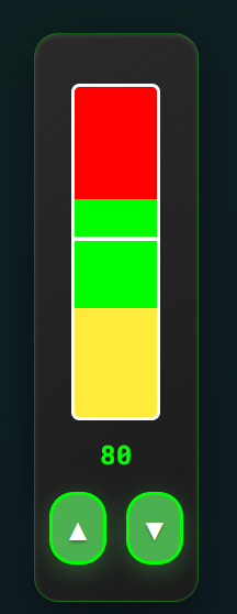
The System display contains the Hydraulic Pressure gauge, the Hydraulic Pump controls, and the Communications Code input, and requires continuous monitoring of two parallel processes.
The Hydraulic Pressure gauge is a vertical bar divided into three labelled regions: Low Pressure (below 90), Correct Pressure (90-110), and High Pressure (above 110). The gauge drops slowly when the Hydraulic Pump is OFF and rises when it is ON. The Communications Code panel shows a three-digit code received via Message, a numeric input field, and a Time Left countdown. You may enter the code up to 15 seconds before the countdown reaches zero; when the timer reaches zero, a button appears and must be pressed without delay.
Worked example: the gauge reads 95, sitting in Correct Pressure (90-110), and the pump is OFF. If you allow pressure to build to 109 before switching OFF, you gain the maximum passive descent interval before the next correction is needed.
When the gauge enters Low Pressure (below 90), you must switch the pump ON. When the gauge reaches 110, you must switch the pump OFF. When the Communications Code countdown reaches 15 seconds, you must enter the code from Message. When the timer reaches zero, you must press the button that appears without delay.
Top Tip: Switch the pump ON when the gauge sits between 90 and 95, allow pressure to rise to 108-110, then switch OFF. This maximises the passive drop interval and reduces the number of pump corrections required per session.
Reading the mechanics is passive; passing requires active cognitive endurance. Access the precise training simulator included in the Air Defence Academy's CBAT/MACTs module.
Start the Simulator, or move to the next guide: CLAN.